Please submit your message online, we will contact you as soon as possible!

Author:A
Automotive electronic control system follows the basic logic of conventional control system, including: perception, control, implementation of three major links. The sensor is used as a sensing unit to obtain the system and environmental state, and the control unit outputs the control instruction by combining the input signal of the sensor and the control logic calculation, and the actuator completes the corresponding action to form a closed-loop control.
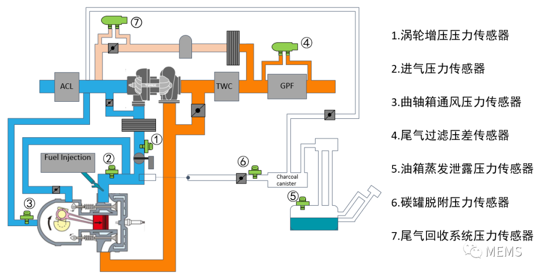
Figure 1: MEMS pressure sensors in powertrain and fuel supply systems that meet National VI standards
Taking the engine management system as an example, the MEMS pressure sensors that will be used are shown in Figure 1, including: Intake pressure sensor TMAP(1&2), turbo pressure sensor EGR TMAP(3), tail gas pressure difference sensor DPF/GPF(4), tank evaporation leakage pressure sensor EVAP(5), carbon tank desorption pressure sensor (6), exhaust gas recovery system pressure sensor (7).
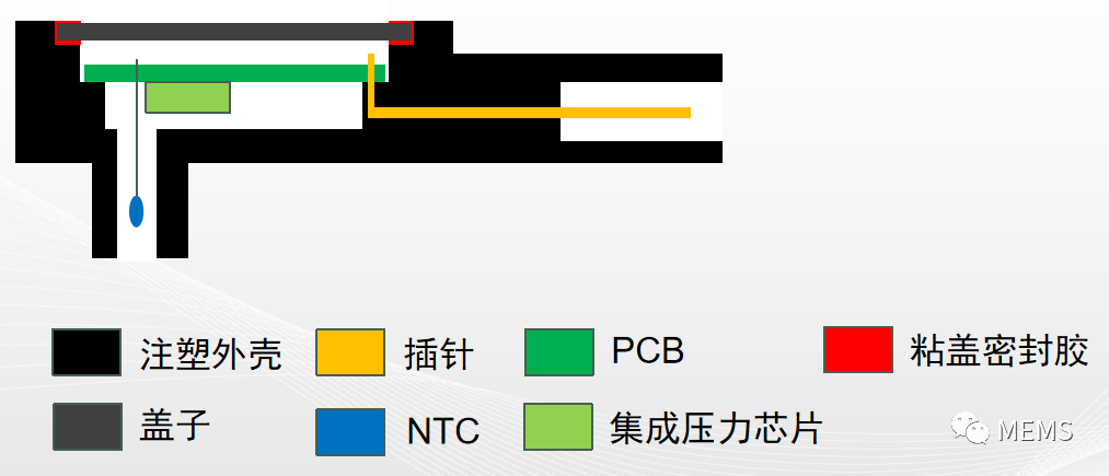
Figure 2: Schematic diagram of typical TMAP sensor structure
The typical structure of the intake pressure sensor is shown in Figure 2. The pressure range required is usually 10~115 kPa, 10~250 kPa and 50~400 kPa, which are respectively applied to naturally aspirated engines, turbocharged engines and engine systems with EGR exhaust gas recirculation. The engine combustion needs to control the air-fuel ratio. The intake pressure sensor is an important signal feedback of the combustion control system, which usually has high requirements on the accuracy and dynamic response time of the pressure detection, and the output is usually in the form of proportional output of 0~ 5V analog voltage, so that when the ADC in the ECU and the pressure sensor use the same VDD as the reference voltage, It can eliminate the error caused by the fluctuation of power supply voltage VDD, which is difficult to completely eliminate in the automotive electronic system.
In addition, with the trend of automotive electronics busization and the increase in the number and accuracy requirements of on-board sensors, SENT interface sensors are used more and more, especially in Powertrain systems. The SENT protocol was first initiated by GM and later became the SAE J2716 standard, which is widely used in automotive electronics. Because of its point-to-point, one-way transmission characteristics, compared with CAN or LIN interface has a better cost advantage, no special transceiver is required, and has a good transmission speed. In addition, because of its single-wire form, the sensor only needs power supply, ground wire, signal line, which can smoothly upgrade the traditional analog voltage output sensor to the SENT output form, the wiring harness, pin and other changes are small, and has more fault diagnosis and data transmission capabilities, becoming the mainstream output form of future powertrain system sensors.
Compared with ordinary IC, MEMS pressure sensors in addition to the principle of differences, the application environment also has a very big difference, taking the intake pressure sensor as an example, which measures a physical quantity rather than an electrical quantity, the sensor requires a special package to change the air pressure into the MEMS sensitive film, and the automotive application environment determines its atmosphere with a variety of potential water vapor and corrosive components. Therefore, it is necessary to coat a protective medium on the MEMS sensitive film to achieve pressure change transmission while protecting the sensitive element from environmental erosion, and to ensure good precision performance and long-term reliability in the full temperature zone and the full pressure range. Automotive MEMS intake pressure sensors usually work in the range of -40 ° C to 125 ° C, and some applications such as engines with exhaust gas recirculation EGR systems will contain exhaust gas components, which will bring higher temperature challenges and more chemical components such as halogen erosion challenges.
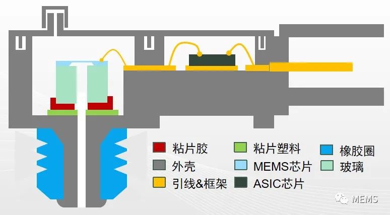
Figure 3: Schematic diagram of the tank evaporation leakage pressure sensor
The Evaporative leakage pressure sensor of the fuel tank is an important part of the Evaporative Emission System (EVAP), and its typical structure is shown in Figure 3. There will be fuel evaporation in the tank, and usually active carbon tanks are set in the fuel system to adsorb the oil and gas, while the activated carbon tank has a certain desorption pressure. Studies have shown that the evaporation of oil and gas emissions is the largest source of VOC emissions from vehicles, and the most important source of urban pollutants such as smog and PM2.5. The United States has adopted strict standards for vehicle emissions earlier, and China's "National six" standards require further improvement of emission indicators, and fuel steam pressure sensors and matching carbon tank desorption pressure sensors have become an inevitable choice.
The range of the fuel steam pressure sensor is small, usually the range used by the ICE internal combustion engine system is -3.75kPa ~ 1.25kPa, and the measured value is the difference between the external atmospheric pressure in the tank, which means that the full scale is only 5 kPa, which belongs to the gauge pressure measurement. Its small measurement range poses a greater challenge to the performance and packaging and calibration of the MEMS pressure sensor itself, and because the application environment is in the tank system, the sensor needs to be able to meet the resistance to corrosive media such as gasoline vapor, and has a wide temperature compensation capability. It is paired with a carbon tank desorption pressure sensor that measures at a range similar to the TMAP intake pressure sensor, typically 115 kPa absolute pressure.
Exhaust aftertreatment systems are also the focus of the "National VI" standard, adding a series of sensors, actuators and control strategies to further reduce emissions and improve combustion efficiency. A more typical MEMS pressure sensor is a differential pressure sensor that monitors the status of a particulate catcher called DPF on a diesel engine system and GPF on a gasoline engine system.
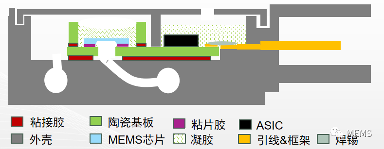
Figure 4: Structure diagram of DPF exhaust pressure differential sensor
Taking a diesel engine system as an example, Figure 4 is a schematic diagram of a typical DPF exhaust pressure differential sensor. The difference sensor assembly structure is equipped with two air pipes, each mounted hose connected to the front and rear sides of the DPF catcher, and the pressure difference between the two ends is reflected to the two sides of the MEMS sensitive diaphragm through the internal structure.
When the DPF is blocked, the pressure difference between the front and rear ends will be very obvious. The typical range of the DPF pressure difference sensor is 100 kPa, which is usually an analog voltage signal with proportional output. The application environment of the sensor is relatively harsh, and the influence of high temperature and corrosive components in the tail gas on the sensor should be taken into account in the design.
In addition to the above fuel vehicle sensor applications, nano micro MEMS pressure sensors can also be applied in HEV hybrid vehicles and BEV pure electric vehicles, such as with start-stop function and brake assist system in hybrid vehicles will use MEMS pressure sensors to detect vacuum degree, new energy vehicles can use MEMS pressure sensors to detect battery pack pressure. For thermal runaway alarm.
To sum up, consult with Kayi Technologies to help provide a full range of solutions suitable for these applications, including MEMS sensors, ASIC signal conditioning chips, and compensation-calibrated integrated sensor chips or custom module forms. And can provide precious metal MEMS resistant to harsh media corrosion and a variety of interface ASics such as SENT, LIN and flexible solutions optimized for application to meet the stringent and high reliability application requirements of automobiles.
Disclaimer | Some materials are from MEMS, reproduced only as industry sharing and exchange, do not represent the views of the company, copyright belongs to the original author. In case of infringement, please contact us. In addition, if you reprint this article, please indicate the source.
If you are interested in this article, please immediatelycontact us

Support Hotline
Please submit your message online, we will contact you as soon as possible!